Physics
Voltage in Resistors Connected in Series
How total voltage is distributed among components.
Mission
Studying how the total voltage of the circuit is distributed among the components of the circuit
Curriculum Alignment
| Standard | Syllabus code | Topic | Coverage | Grades | |
|---|---|---|---|---|---|
| NGSS | HS-PS3-6 | HS-PS3-6 (Ohm's law; potential difference in series/parallel circuits) | Full | 9–12 | |
| British / IGCSE | 0625 §4.3.2 | CAIE IGCSE Physics 0625 — 4.3.2 Supplement #8b: total p.d. across series circuit = sum of individual p.d.s | Full | 9–10 | |
| IB | DP B.5 | DP Physics — Theme B.5 Current and circuits | Full | 11–12 | |
| CBSE | Class 10 Ch 12 | CBSE/NCERT Class 10 Science — Ch 12 Electricity (voltage distribution in series) | Full | 10–10 | |
| AERO / AP | AERO Science | AERO K-10 Science Framework — Physical Science: electric circuits (general strand, no numbered PE) | Full | 9–10 |
Variables
What you change
- Resistance value
What you measure
- Voltage Drop
What you keep constant
- Wire length
- Wire cross section
- The voltage of the power source
- Temperature of wire
Equations
V_1 = Voltage drop on first resistor (V)
V_2 = Voltage drop on second resistor (V)
V_3 = Voltage drop on third resistor (V)
V_Bat ≈ 6 Volts
R_1, R_2, R_3 = Resistors (ohm)
V_1 = \frac{V_Bat}{R_1+R_2+R_3}*R_1
V_2 = \frac{V_Bat}{R_1+R_2+R_3}*R_2
V_3 = \frac{V_Bat}{R_1+R_2+R_3}*R_3
V_1+V_2+V_3 = V_Bat
What You'll Need
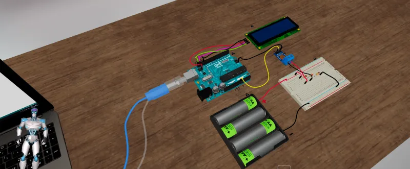
- Breadboard 400 Tie Point
- Arduino Uno
- I2C LCD
- 25V Voltage Sensor Module
- Resistor
- 6V Battery Pack, 4x AA
Mind-Blowing Fact
Shocking!!
Nikola Tesla wanted to wire the walls of classrooms with high-voltage lines to enhance the intelligence and health of school children by exposing them to electricity. This idea was accepted by William H. Maxwell, the then-superintendent of New York City schools.
How You Can Run It
Virtual modeTest modeExercise modeView-only modeAccessibility modeTobii eye trackingVoice commandsArduino integrationAmericanBritishIB